Make A Decision Now! Update Your Production Line Or Not?
Inquiry is free, what about checking the price first?

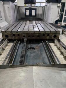
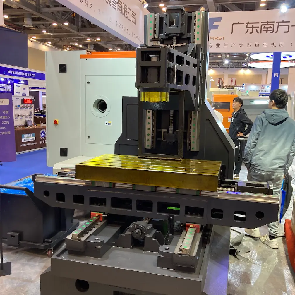
Linear guideways are widely used on CNC machine tools, even gantry machining centers. Gantry machining centers are usually equipped with four horizontal linear guideways with a total length of up to 12 meters, which can be extended to meet different travel and functional requirements. After mastering the installation skills of linear guideways for this type of machine tool, the installation of linear guideways of other specifications will become easy and effective.
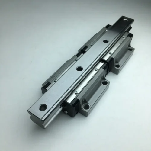
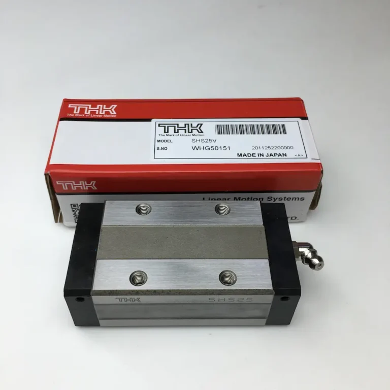
Next, we will explore the uniqueness of the linear guideways of this length. Its design adopts a four-row single arc tooth contact, combined with an optimized structure, to achieve a significant increase in heavy load capacity, which is more advantageous on gantry machining centers than other linear guideways. In addition, it also has four-way equal load characteristics and an automatic centering function, which can effectively absorb the assembly error of the installation surface and ensure that high-precision requirements are met.
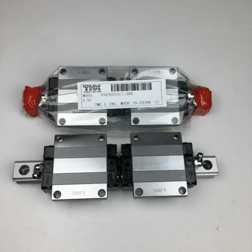
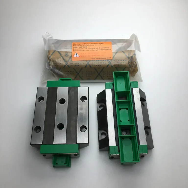
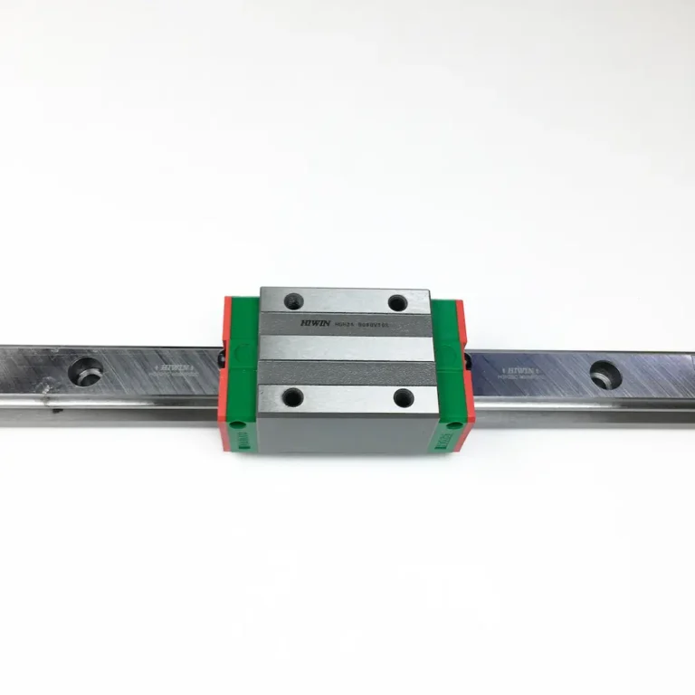
The linear guide blocks adapted to this specification of linear guideways are usually flange-type design, which can withstand overweight loads, and their fixing method is a top-locking design, which is a widely used locking and fixing method. This type of linear guideway with a total length of 12000mm is generally supported by 4 linear guide blocks, but the linear guideway’s stroke length has no direct relationship with the number of linear guide blocks, which depends entirely on the processing requirements.
Assuming that a linear guide block with ZB preload class (preload 0.10C-0.12C) and Precision Class P (0.027) is selected, let us take a closer look at the preparations before installation.
The calibration of the machine level is crucial. Place two equal-height blocks and a marble ruler on the mounting base, and then place a precise level to adjust the base level, requiring the base to be convex by 2~3 grids.
Check the roughness, flatness, straightness and appearance of the linear guideways installation base surface. After the leveling adjustment is completed, the laser interferometer is required to accurately measure the flatness and straightness of the main rail installation base surface, and at the same time ensure that the roughness reaches 1.6 and the appearance has no casting defects.
Handle the chamfers of the linear guideways installation base surface and the linear guideways side reference installation surface. The chamfer radius should be less than or equal to 3.5mm, avoid being too large or protruding, to ensure the good installation of the linear guideways precision and prevent the interference of the linear guide blocks.
Process the mounting threaded holes of the linear guideways installation base surface. Confirm that the screw hole position is correct, the center distance is 120mm, and use CNC equipment for high-precision screw hole processing.
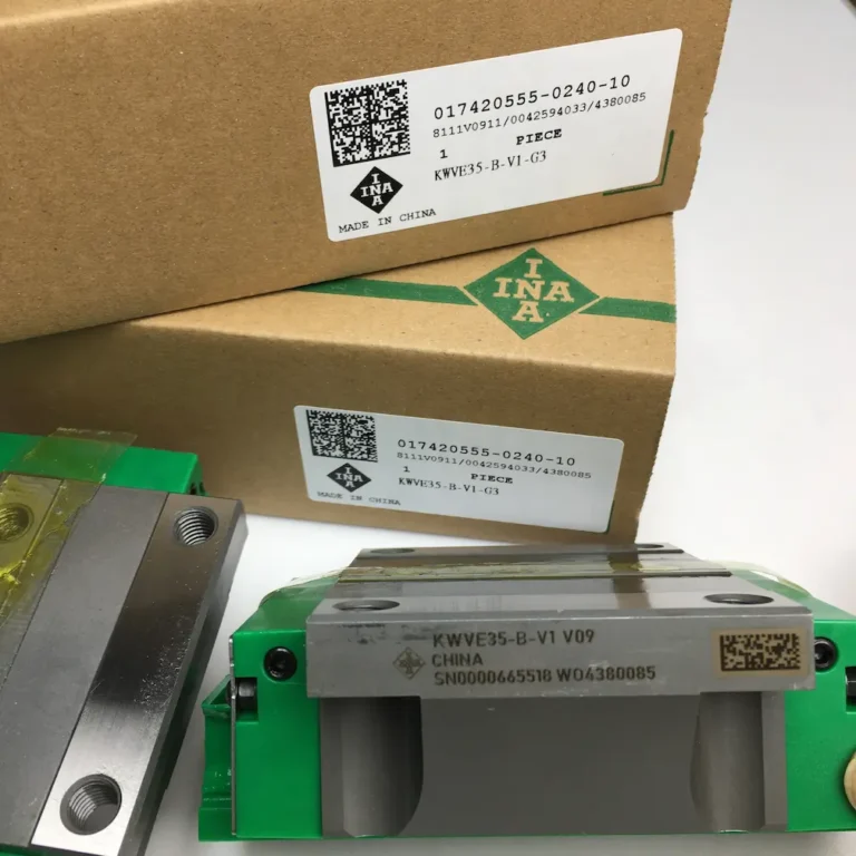
After unpacking, carefully check the linear guideways to confirm whether there is a certificate of conformity, whether it is bruised or rusted. Clean the corrosion-preventive oil, remove burrs, surface protrusions and dirt on the assembly surface, etc.
Finally, perform alignment adjustment, lubrication, and protection work on the linear guideways.

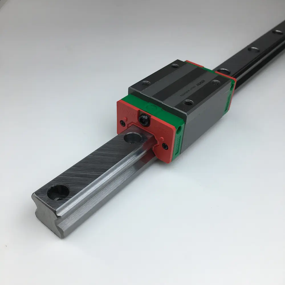
When extending the linear guideways, it is necessary to ensure that the numbers of the same set of guide rails are continuous and the butt ends are connected to ensure the accuracy of the linear guideways.
It is worth noting that this linear guideway with a total length of 12,000 mm is actually made up of four linear guideways. During installation, it is necessary to ensure that the joint position of each linear guideway is staggered with the adjacent linear guideways to avoid the accuracy reduction caused by the installation error of the linear guideways when the bed runs to the joint. In addition, a gap of 0.03 to 0.05 mm must be reserved at the joint position of the linear guideways, which is usually measured with a feeler gauge, which can effectively prevent the axial length change caused by the thermal expansion of the linear guideways.
Accurately distinguish between the reference guide rail pair and the non-reference guide rail pair. The reference guideway will be marked with the MA logo, and the linear guide blocks will be equipped with a polished reference side. During installation, the reference side of the linear guideways should be fitted with the reference side of the mounting base step, aligned with the corresponding screw holes, and the linear guideways should be lightly fixed with bolts. Then, the other three linear guideways are placed on the base surface in a free manner.
Correction of the main guideway. During the correction of the main guideway, a laser interferometer must be used for linear length measurement to ensure that the full stroke straightness is controlled within the range of 0.03-0.05, and a convexity of 0.03 is allowed. At the same time, a torque wrench should be used to tighten the screws with a specific torque, and one side of the guide pair should be tightened by a wedge. Although ordinary linear guideways may be corrected with a lever-type dial gauge, the correction method is similar to that of the main guideway.
After completing the correction of the main guideway, the main guideway should be used as a reference and the other three linear guideways should be corrected one by one using the same method.
Then, the correction of the four linear guideways should be carefully checked to confirm whether the fastening screws and wedge tightening screws of each linear guideway are complete, and ensure that the screws have been tightened at a specific torque. After the inspection, install a dust-proof hole plug designed for dust prevention at the countersunk hole of the linear guideways.
Next, install the linear guide blocks (i.e., worktable, spindle box, etc.). Place the worktable steadily on the plane of the linear guide blocks, align the mounting screw holes, and tighten them with light pressure. Then, tighten the locking device on the side of the linear guide blocks on the reference side so that the reference side of the linear guide blocks fits tightly against the side base of the worktable. Finally, tighten the screws on the linear guide blocks on the reference side and non-reference side one by one in diagonal order.
After installation, check whether the linear guide blocks run smoothly throughout the entire stroke and whether there is any gap or obstruction. At the same time, ensure that the friction resistance remains stable throughout the entire stroke without significant changes. If any abnormality is found, it should be promptly investigated and resolved to avoid potential problems. After meeting the above requirements, the accuracy indicators such as the straightness and parallelism of the worktable can be further checked.
In order to ensure the stable operation of the machine tool and extend its service life, the lubrication lines of each linear guide block need to be connected. This can not only reduce friction resistance, reduce drive power, and improve efficiency, but also reduce linear guideway wear, prevent corrosion, and avoid creeping at low speed and heavy load, and thermal deformation at high speed.
In addition, to prevent damage to linear guideways by cutting, dust and other debris, linear guideway protection devices should be installed. This includes installing wipers or protective covers at the ends of the moving guide rails to ensure that the linear guideways are not exposed, thereby keeping them clean and intact.